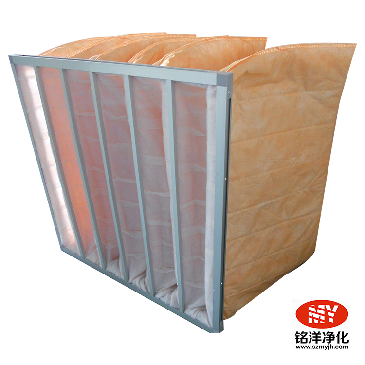
Key takeaway: Establish the selection order from system objectives and downstream protection needs. For the question "How to choose F5 F6 F7 F8 F9", the safest approach is to first confirm the installation location, project documentation, and field data, then decide under comparable operating conditions; do not base conclusions solely on a product name, a single number, or a fixed date.
1. Clarify the applicable scope first
Selection should be driven by on-site requirements, not by choosing the seemingly higher-grade or lower-cost product first. Dimensions, airflow, pressure drop, installation structure and maintenance accessibility must all be checked together.
When addressing requests like "How to choose F5 F6 F7 F8 F9", procurement or technical personnel should consolidate the installation location, actual airflow, dimensions, efficiency, initial pressure drop, frame or sealing structure, environmental conditions and maintenance window into a single specification sheet. For these scenarios, balance pressure drop, dust-holding capacity and protection of the downstream HEPA stage. If information gaps exist, complete them before ordering or modifying rather than attempting trial-and-error during installation.
In any protection stage located in the intermediate filter section of an air handling unit and upstream of the HEPA stage, product parameters must be understood together with the actual installation location, system airflow, upstream and downstream conditions, and site management requirements. Especially in controlled environments, continuous operation, or change-managed scenarios, treat this article as a communication and inspection framework, and use approved project documents, equipment data and site measurements to determine final actions.
2. What information should you check on site?
| Inspection dimension | Items to verify | Common pitfalls |
|---|---|---|
| Specifications and site conditions | Confirm dimensions, rated airflow, required efficiency or function, installation structure and maintenance accessibility. | Do not assume similarly named or similarly sized products are interchangeable. |
| Operating data | Record baseline and observe differential pressure, airflow, equipment operation or area condition under comparable conditions. | A single reading should not be interpreted without considering fan speed, damper position and upstream load. |
| Installation and sealing | Check orientation, positioning, clamping, seals and frame/rail condition. | Distinguish between media defects and bypass leakage of unfiltered air. |
| Maintenance closed loop | Keep records of inspection, corrective actions, replacements and any required re-testing. | Before an abnormal shutdown, ensure the system is restored to project-required conditions. |
From a data-management perspective, baseline values and trends are more valuable than a single "high" or "low" reading. Any abnormal reading should be rechecked under the same or comparable operating state — for example fan speed, damper position, operating time, upstream filter condition and instrument tapping conditions. Only then can maintenance personnel distinguish real load changes from measurement or system-state changes.
3. Recommended inspection and handling workflow
Confirm boundaries. First review project documents, equipment manuals and site maintenance procedures to clarify the purpose, permitted conditions and safety requirements of this inspection or task.
Collect baseline. Record bag or cartridge form, frame sealing, clamping state, differential pressure trend, rated airflow and upstream operating state; if no historical baseline exists, establish comparable initial data first.
Layered verification. Verify step-by-step from the upstream environment, equipment condition, filter or component appearance, installation sealing to downstream performance — avoid skipping basic conditions and drawing conclusions prematurely.
Implement corrective actions. When replacement or adjustment is needed, verify product specifications and installation orientation; control contamination, mechanical stress and debris risk during removal and installation.
Restore and record. After completion, check system restored state; in scenarios requiring validation, arrange the appropriate airflow, integrity/leak test or environmental performance verification per project documents.
For filters to be replaced, verify model, dimensions, rated airflow, filtration grade or function, outer frame and sealing method before disassembly. For non-standard requirements, also provide installation drawings, rails or clamping method, equipment location and maintenance clearances. Installation completion is not the end of the task — data verification after restoration, cleanup and record-keeping are essential parts of the maintenance closed loop.
4. How does this interface with related products or solutions?
This topic can be understood in conjunction with the existing F5 bag-type medium-efficiency filter, F7 medium-efficiency filter, F9 medium-efficiency filter. Upstream filters, intermediate filters, terminal filters or clean equipment each play different roles; when selecting, modifying or confirming non-standard sizes, consolidate site parameters and consult with technical staff. Technical recommendations should be based on real operating conditions, not a generic article substituting on-site verification.
5. Frequently asked questions
Can I rely solely on fixed replacement intervals?
Not recommended. Combine project documents, equipment manuals, differential pressure trends, airflow or environmental capability, installation condition and abnormal events when making decisions; fixed intervals can serve as triggers for planned inspections but cannot replace on-site confirmation.
Must a filter be replaced immediately after an abnormality?
First confirm the nature and risk level of the abnormality. For cases involving damage, moisture, obvious bypass leakage, or potential impacts to a controlled environment, follow site procedures to isolate and organize assessment; for anomalous readings, also verify instruments, fan, dampers and upstream/downstream filter conditions.
What maintenance records should be retained at minimum?
It is recommended to retain equipment or installation location, product model and batch, dimensions and rated parameters, installation date, initial differential pressure, inspection readings, abnormal handling, replacement personnel and any required re-test results to form a traceable closed loop.
6. Conclusion
The core of "How to choose F5, F6, F7, F8, F9 medium-efficiency filters? Efficiency, pressure drop and application comparison" is not to find a decontextualized standard answer, but to establish a repeatable, traceable, and closed-loop judgment method. Check bag or cartridge form, frame sealing, clamping state, differential pressure trend, rated airflow and upstream operating state, and connect technical specifications, site status and maintenance records to better support stable system operation.
References and scope of use
This article is intended for technical communication and maintenance planning of air filters and clean equipment, and does not replace project design documents, equipment manuals, on-site risk assessments or applicable regulations and quality system requirements. Cleanroom air cleanliness classes may be referenced in ISO 14644-1; HEPA filter testing and performance documentation can be cross-checked with EN 1822 / ISO 29463 related guidance.