Conclusion up front: Efficiency labels must be interpreted together with the actual particle ranges and system requirements, not judged by the numeric value alone. For "ISO16890 ePM1 ePM2.5 ePM10", the safest approach is to first confirm the installation location, project documents and on-site data, then make assessments under comparable operating conditions; do not draw conclusions based solely on a product name, a single number, or a fixed date.
1. Clarify the scope of the question
This is a basic but easily oversimplified topic. The goal of understanding the principle is not to memorize an isolated parameter, but to know which conditions that parameter should be evaluated with in the system.
Regarding "ISO16890 ePM1 ePM2.5 ePM10", it is recommended to first place the product or concept in the actual location within an air handling unit, fresh air unit, or cleanroom supply system. Consider the filter as part of a system that includes the fan, dampers, cabinet, filter section and terminal devices. When comparing, first look at the filtering or equipment function it is intended to serve, then check rated operating conditions, available installation space, sealing method and subsequent maintenance conditions. This yields a selection logic suited to the current system rather than an absolute conclusion taken out of context.
In any air handling unit, fresh air unit, or cleanroom supply system, product parameters must be understood together with the actual installation location, system airflow, upstream and downstream filter condition, and on-site management requirements. Especially where controlled environments, continuous operation, or change management are involved, use this article as a framework for communication and inspection, and rely on approved project documents, equipment manuals and on-site measurements to determine final actions.
2. What information should you check on site?
| Inspection dimension | Items to verify | Common misconceptions |
|---|---|---|
| Specifications and site conditions | Confirm dimensions, rated airflow, efficiency or functional requirements, mounting structure and accessibility for maintenance. | Do not assume products with similar names or identical dimensions are interchangeable. |
| Operating data | Record baseline state and observe differential pressure, airflow, equipment operation or zone condition under comparable operating conditions. | A single reading should not be interpreted without reference to fan speed, damper positions and upstream load. |
| Installation and sealing | Check orientation, positioning, clamping, sealing elements and the condition of frames/tracks. | Distinguish between problems with the filter media itself and bypass leakage. |
| Maintenance closed loop | Keep records of inspections, actions taken, replacements and any required retesting. | Before declaring abnormal shutdowns, confirm the system has been restored to project-required conditions. |
From a data management perspective, initial values and trends are more valuable than a single "high" or "low" reading. Any abnormal reading should be rechecked under identical or comparable operating conditions — for example fan speed, damper positions, operating period, upstream filter condition and pressure tapping method. Only then can maintenance personnel distinguish real load changes from measurement or system condition changes.
3. Recommended inspection and disposition workflow
Define the boundaries. First review project documents, equipment manuals and on-site maintenance procedures; clarify the purpose of the inspection or work, permitted conditions and safety requirements.
Collect baseline data. Record the initial pressure drop, operating conditions, airflow, upstream and downstream filter status, installation sealing and maintenance records; if no historical baseline exists, establish a comparable initial dataset.
Layered verification. Verify sequentially from upstream environment, equipment condition, filter or component appearance, installation sealing to downstream performance; avoid skipping basic checks and jumping to conclusions.
Execute disposition. When replacement or adjustment is needed, verify product specifications and installation orientation; control contamination, mechanical stress and foreign material risk during removal and installation.
Restore and document. After completion, verify system restoration status; where verification is required, arrange corresponding airflow, integrity/leak test, or environmental performance retesting per project documents.
For products that require replacement, verify model, dimensions, rated airflow, filtration class or function, frame and sealing type before disassembly. For non-standard requirements, supplement with installation drawings, tracks or clamping methods, equipment location and maintenance clearances. Installation completion does not mean the work is finished — post-installation data verification, site cleanup and records close the maintenance loop.
4. How this links to related products or solutions
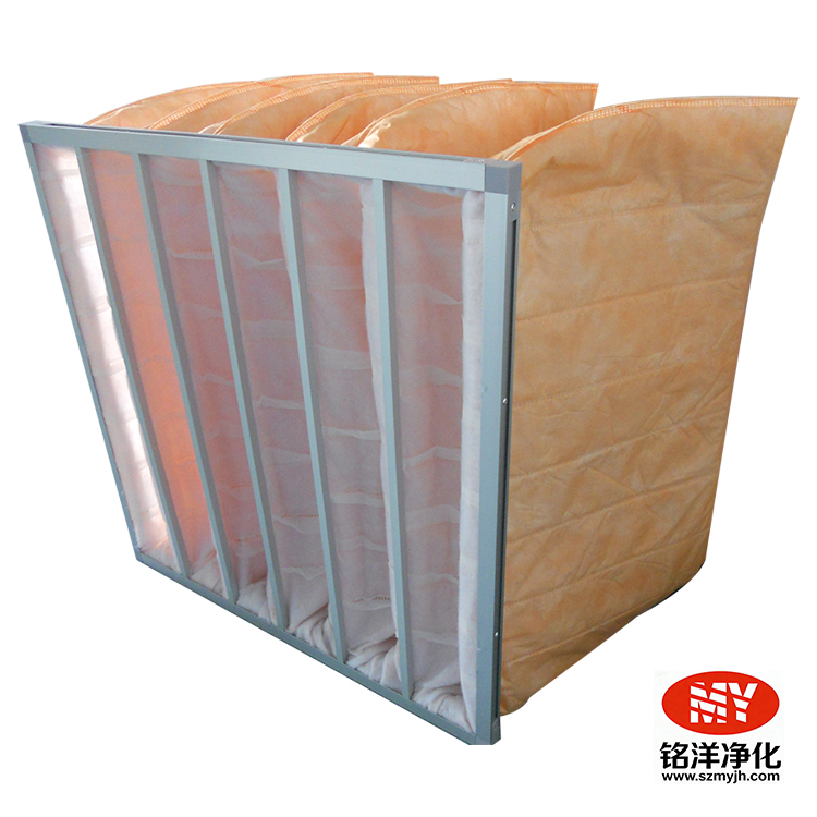
This topic can be considered together with existing F7 medium-efficiency filter and F9 medium-efficiency filter. Front-end filters, intermediate filters, terminal filters and clean equipment each have different roles; when selecting, modifying or confirming non-standard sizes, organize the site parameters and consult technical personnel. Technical recommendations should be based on actual operating conditions, not substitute for on-site confirmation with generic articles.
5. Frequently asked questions
Must a filter be replaced immediately when an abnormality appears?
First confirm the nature and risk level of the abnormality. For damage, moisture ingress, obvious bypass leakage or situations that may affect a controlled environment, follow site procedures to isolate and organize an assessment; for anomalous readings, also check instruments, fan, dampers and upstream/downstream filter status.
What minimum maintenance records should be kept?
It is recommended to retain records of equipment or installation location, product model and batch, dimensions and rated parameters, installation date, initial pressure drop, inspection readings, abnormal disposition, replacement personnel and any required retest results, creating a traceable closed loop.
Can maintenance be done only on a fixed schedule?
Not recommended. Combine project documents, equipment manuals, differential pressure trends, airflow or environmental capability, installation condition and abnormal events to make decisions; fixed intervals can be used as triggers for planned inspections, but should not replace on-site confirmation.
6. Conclusion
The core of "How to read ISO 16890 ePM1, ePM2.5, ePM10? Interpreting air filter efficiency labels" is not to find a context-free standard answer, but to establish a repeatable, traceable and closed-loop evaluation method. Verify initial pressure drop, operating conditions, airflow, upstream and downstream filter status, installation sealing and maintenance records, and connect technical specifications, site condition and maintenance records to provide more reliable support for stable system operation.
References and scope of use
This article is intended for technical communication and maintenance planning of air filters and clean equipment; it does not replace project design documents, equipment manuals, on-site risk assessments or applicable regulations and quality system requirements. Cleanroom air cleanliness classifications can be referenced in ISO 14644-1; HEPA filter product testing and performance data can be cross-checked with EN 1822 / ISO 29463 related guidance.